


How to make wireless low power Arduino
27. června 2016Lang: cs
How to make wireless Arduino with extra low power.
Warduxere is a programmable device for wireless communication with a small bitrate, extra low power consumption and an option of battery power source. It is a foundation designed to be used in development of wireless projects.
Specifications
- Power: DC 3,4-6V
- frequency of wireless communication: 433MHz
- Range: up to 900 m
- Consumption: run mode 5 mA; Broadcasting 10 mA; sleep 10uA
- the dimensions: 25 x 25 mm
- Communication Interface: serial line, 3.3V
- Development is possible on any OS and on non-x86 PC as well
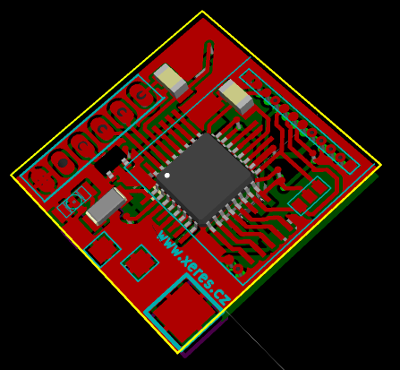
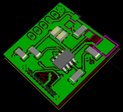
3D models of devices:
Motivation
Nowadays modern devices include wireless peripherals and wireless connection is gradually becoming a common thing.
These devices always consist of a microprocessor and a wireless part.
I've already used commercial solutions for these purposes, but I was not satisfied and even on the internet I haven't found an adequate which would meet all of my requirements. That's why I decided to create a platform that can be reused in the implementation of different wireless projects.
Criteria for the device:
- The compiler must be: free, multiplatform, without conditions, supported by the manufacturer of the processor.
- Cross platform development tools (IDE).
- Standardized hardware and software for programming.
- Easy to develop - higher programming language, the availability of libraries and plug-in devices.
- Open solution.
- A small device.
- Energy efficient equipment that will last long on battery power.
- Precise measurement of battery.
- Wireless communication.
- The ability to connect various peripherals.
- Standard work with memory = DMA .
- Large number of basic components and large user community.
Hardware choice
There is a very famous and successful Arduino Project . Arduino is based on 8bit processors by Atmel company, which is actively involved in development of the opensource tools for developers, for example the GNU GCC compiler for AVR. These development tools run on all operating systems of various computer architectures. For Arduino there is developed Arduino IDE, which is multiplatform. There is even no need of a special hardware or a special software programeer or a special driver for programming. The entire device can be started and used immediately without any installation. Arduino uses Wiring language as its main programming language, which is similar to the C++. There is still need to know the coding but thanks to Wiring it is possible to learn it easily with Arduino. (You can find more detailed information on Arduino in PE / AR 2009/1).
Therefore I have decided to use Arduino as a base and thus AVR microcontrollers from Atmel.
Originally I thought I will use existing prototype components,
but it turned out that I have to develop my own device.
Because for example Arduino Pro Mini version contains a power diode and a wasteful
stabilizer, that together create large and totally unnecessary power
consumption, and therefore it is unsitable in case of long-term battery power supply.
I have created a device with an AVR processor,
which is energy efficient and also contains several other components.
At the same time the device is compatible with Arduino.
And because the most important part is the Wireless part , I named the device Warduxere.
Because of compatibility with Arduino it can use already existing and proven development tools:
Arduino IDE, libraries etc. It is also possible to connect many other devices, that already have their API libraries.
Processor
The device is controlled by a microprocessor Atmega 328P in the TQFP package. In
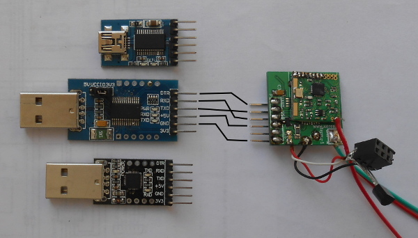
the microprocessor there is loaded a bootloader, which is used for comfortable loading of the program using a serial line. For PC connection it is best to use USB-UART converter, which supplies power to the Warduxere as well. I use a converter with the FTDI 232RL chip or the CP2102 chip.
You can also connect the device to the computer's parallel port, but you have to provide the power supply and use a voltage convertor, for example in connection with the MAX232 chip (already described in
Article in PE / AR 2010/12).
After connecting Warduxere to the USB converter no other electronics is needed and you can connect Warduxere to the PC and use it along with Arduino IDE.
You can see the connection on the picture below, it is necessary to connect RX to TX correctly.
For computers such as
Raspberry PI and
Banana PI you can connect Warduxere directly without any additional electronics, because these computers have hardware serial lines using the 3.3V voltage levels.
For uploading the program to the processor there is the "upload" button in the development environment. At first IDE resets the processor using the DTR (RTS) outlet. After a reset the boot loader is started and waits a while for the loading of the program.
Wireless
On the market it's possible to purchase different wireless chips, usually even as prepared modules.
Some of them communicate in one direction only, some can also use Wifi, ZigBee or other standards.
They differ in their frequency and interface through which they can be connected to a microprocessor.
I chose SI4432 chip. This chip can both transmit and receive.
With the processor it communicates via SPI bus and works on frequencies 240-930 MHz, has a great reach and an output power + 20 dBm .
It also has a low supply voltage 1.8 to 3.6 V and a low power consumption .
I have bought already prepared small DRF4432F20 module which contains the SI4432 chip and is ready to work at a frequency of 433MHz.
For Arduino there are libraries for working with this chip, namely
the library Radiohead RF22.
Parameters of the wireless module DRF4432F20 with SI4432 chip:
- Supply voltage: 1.8 ~ 3.6V
- Working frequency: 433MHz or 868MHz
- Modulation: FSK / GFSK / OOK
- SPI interface
- Sensitivity: -121dBm
- Output power: + 20dBm
- Data transfer rate: -0.123 ~ 256 kbps
- Digital RSSI
- Wake-up Timer
- 64 bytes of TX / RX FIFOs
- Integrated voltage regulator
- Frequency Hopping
- Temperature Sensor and 8-bit ADC
- Operating temperature: -20 ° C ~ + 60 ° C
- consumption during standby: ≤ 1uA
Pins of the wireless module are connected to inputs of the CPU 6->16, 7->15, 8->17, 9->14, 10->32. The module is powered by a stabilized voltage of 3.3V. Pins 11 and 12 of the wireless module are connected to the ground. Pin 5 is connected to 3.3V.
The layout of the pins of the DRF4432F20 module, see figure:
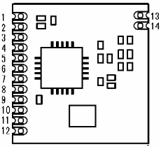
Wireless module is supplied including antenna, which is connected to the pin no. 13.
Construction
Everything is chosen with regard to the size and especially to the energy efficiency. Therefore the processor and the entire device operates at 3.3 volts and clock frequency of the processor is set to 8MHz.
It uses an internal oscillator, which saves space on the PCB and the structure is simpler.
It is expected to use one LiPo cell as a power source.
These batteries have a suitable voltage, large capacity and small size.
Also contrary to NiMH batteries they do not suffer from self-discharging, which is important in the long term use. After charging the voltage on LiPo battery reaches 4.2V (according to battery type and settings of charging program).
When discharging these batteries still maintain a sufficient operating voltage which should not drop below 3.3V. When it drops to 3.6V it is appropriate to re-charge the battery.
Therefore, these parameters make LiPo batteries a suitable candidate as an energy source.
To reduce the power consumption the Warduxere has no power diode.
The device includes voltage stabilizer MCP1700 , which has a small power consumption. The choice of a stabilizer defines the input voltage, which can be 6V maximally.
Specifically, it is the stabilizer MCP1700T-3302 / TT.
These are its values according to the documentation:
- typical quiescent current of 1.6 uA
- maximum output current of 250 mA
- drop 178mV at 250 mA
The device includes operational amplifier MCP6042, which has according to the documentation quiescent current of 600 nA . If the energy efficiency is not a crucial thing, you can replace the operational amplifier by a cheaper and more affordable type, for example MCP6002 or MCP6L02.
For low consumption you have to chose large resistors (R5, R6) at the divider for the battery measurement, for example of a value 1M Ohm.
Printed circuit board
PCB is designed to be fitted even at home without any problem. Therefore the used components are in large SMD 1206 packages, which are located in such way that they can be soldered easily. It is a double-sided printed circuit board with plated holes. On a well-made board with a non-solder mask you can easily solder even a processor in a TQFP package. The wireless module has to be soldered as the last one, the order of soldering of other components does not matter.
Assembling and starting
Starting of the device consists of following steps:
- Soldering of the CPU and other components besides the wireless module
- Burning the loader
- Test by the blinking program
- Soldering of the wireless module
- Testing of the wireless module
When mounting the components, start with soldering the processor (IC2), which you will fit into place precisely and with the correct orientation using the tweezer, and first of all solder two pins in opposite corners. After checking that the position is precise solder the remaining pins of the processor. Then solder the U1 stabilizer. Then you easily solder all remaining components on this side of the PCB. Just be sure to properly orient the LED. On the other side start by soldering of the operational amplifier (OP1). Mind the correct orientation and proceed as with the processor. Then solder the remaining components on this side of the board.
Boot loader
The easiest way is to solder the processor with already pre-programmed bootloader, but it is also possible to program the processor even after it is soldered to the board as there are pins on the board prepared for this.
To upload the boot loader you need a hardware and a software programmer. For example you can use the parallel port of the computer and pony-STK200 software and Avrdude . Everyone will probably use the programming resources he is already familiar with.
As a programmer you can use Arduino itself. You load
ArduinoISP software
into Arduino and after connecting both devices together you run the burning of the boot loader directly from the Arduino IDE.
Outlets of the programmer have to be connected to the pads within K1. CPU pins are in order from left: 15 MOSI, 16 MISO,
17 SCK. These pins have to be connected to the programmer. In case of Arduino ISP they are D11 (MOSI), D12 (MISO), D13 (SCK).
Then you have to connect the power (until stabilizer is not soldered yet you can use a pad at R4 resistor) and GND.
The last one is the processor reset, which can be connected for example to pad of C3 capacitor.
As a reset in Arduino ISP is used pin D10.
Now you can burn the bootloader.
The loader is standard bootloader for Arduino. The processor is set to 8MHz with
internal oscillation.
Before burning the bootloader you have to select the right type of device in the Arduino IDE , that defines its parameters.
Simply add following text into arduino/hardware/arduino/boards.txt file:
atmega328Wb.name=Warduxere by www.xeres.cz
atmega328Wb.upload.protocol=stk500
atmega328Wb.upload.maximum_size=30720
atmega328Wb.upload.speed=57600
atmega328Wb.bootloader.low_fuses=0xE2
atmega328Wb.bootloader.high_fuses=0xDA
atmega328Wb.bootloader.extended_fuses=0x05
atmega328Wb.bootloader.path=atmega
atmega328Wb.bootloader.file=warduxere.hex
atmega328Wb.bootloader.unlock_bits=0x3F
atmega328Wb.bootloader.lock_bits=0x0F
atmega328Wb.build.mcu=atmega328p
atmega328Wb.build.f_cpu=8000000L
atmega328Wb.build.core=arduino
atmega328Wb.build.variant=standard
These values define all device's configuration for uploading the bootloader, the processor settings (lock bits), compilation of the program and the speed of uploading. The file
warduxere.hex with the bootloader including a blinking LED software is available for download on the website of the magazine PE / AR.
After connecting USB-UART converter to the pins of the P1 connector you can upload programs to the processor and test the basic functionality by LED blinking. Outlets are in following order: GND, NONE, VCC, TX, RX, DTR. Remember that it is necessary to connect the CPU's RX to convertor's TX and vice versa.
At last solder the wireless module. Just to be sure attach a strip of insulating tape to the bottom of the wireless module. Solder it so that it touches the processor, this will considerably reduce eventual mechanical stress in joints. Then verify the functionality by uploading a sample program. If for example the module is wrongly soldered, the sample program will send message through the serail line about the problem with its initialization.
Now you have the device ready and you can start to create simple but also wide wireless sensor networks ...
Power consumption
I have roughly measured the wireless module's consumption at voltage of 3.3 V, values were following: 9 mA when broadcasting; 1.4 mA when idle, according to documentation 1uA when sleep. Processor at 5V when sleep draws 0.16 mA , after turning off the ADC it draws approximately 1-2 uA. After optimization to minimize the power consumption and when connecting only the processor and the wireless module I have measured the consumption of 3.4 mA at idle state and during sleep of processor and wireless module I have measured 5uA . Approximately when neglecting other effects Warduxere could work several years when powered from a single LiPo cell, such as those in phones. In real use however it mostly depends on the particular application and this determines real endurance on battery power. Further thing are the connected peripherals that have to be asleep or power efficient.
For fully fitted Warduxere in sleep state I have measured consumption of less than 10uA .
Application
To work with the device just download from internet
Arduino IDE,
which contains everything you need. Just unzip the downloaded archive, there is no need to install anything.
Besides all the necessary components Arduino IDE contains numerous examples for Arduino itself and for the common expansion boards (shields).
Warduxere is fitted resistor and solder pads for one-wire bus, resistive divider for battery measuring, resistor and solder pads for analog sensor (eg. photoresistor).
I brought out other pins of the processor to the solder pads, so that it is possible to connect to the processor other devices and peripherals, such as
various types of LCD displays, Ethernet, GSM modules.
Specific use will depend mainly on the ideas of each designer. Further I am going to describe the properties that distinguish Warduxere from Arduino.
Before using the libraries mentioned in the following paragraphs you have to unzip them to the arduino/libraries/ folder.
LED
The functionality of the device can be simply tested by LED's blinking. Usually diode is on
CPU 17 pin (on Arduino it is custom to label it D13), but there is connected the
wireless module. Therefore, in Warduxere LED is connected to pin 32 (Arduino D2). See sample program Blink .
Wireless
The configuration options of the wireless communications are extensive.
Most importantly, the communication is packet-oriented with a buffer of 64 bytes.
The speed of communication can be 0.123 up to 256 kbps, the modulation: FSK, GFSK and OOK.
It is possible to operated even extensive MESH networks.
For example I will mention only the most basic type of communication, with which you can verify the functionality of the device. See sample programs Wireless-client and Wireless-server .
Other practical examples of using the SI4432 chip with Radiohead RF22 library will reader find in the
documentation on the Internet.
Low power modes
The processor can do several power-saving modes.
The most power saving mode od the CPU is sleep, to save even more it is needed to put in sleep individual parts of the processor as well, such as A/D converter and Brown-out Detector (BOD).
Often it is enough to leave only the watchdog running, which will generate interruption to wake up.
It is also needed to pur the peripherals to sleep as well, in this case it is only the wireless module which can sleep on demand. When suspending the system it is therefore needed to put to sleep the processor itself and the wireless part. For simple suspend program see program Sleep .
Who does not want to deal with suspend settings himself can use the library
Low-Power.
Battery
The battery state is detected by measuring voltage 1:1 at divider using the analog converter of the CPU. Using this connection the actual voltage on battery is measured.
It is thus possible to connect for example three NiMH cells or single LiPo cell or even other types of batteries
and by adjusting the software you can easily achieve the specific needs for monitoring the battery state.
In other solutions, where the battery voltage is measured behind the 3V stabilizer, there was a problem especially when using LiPo batteries.
For accurate measurement of the battery is also required to have precise divider .
Basic series of the resistors have a tolerance of +-5%, but these less accurate resistors can cause a considerable error in measurement. In worst case up to +-10% which at 4V battery means 0.4V and that is really a lot. This is inacceptable when measuring the state of LiPo batteries. Therefore it is necessary to use precise resistors with a tolerance of +-0.1%, eventually +-0.5%.
But there is no need to buy expensive precise resistors right away. For the production of several devices it is sufficient to measure resistors and create pairs with those of the equal value.
Battery voltage measurement is in sample program Battery .
You can easily try all the examples if you have Arduino Pro Mini 3.3V 8MHz or microprocessor Atmega 328P and you will connect them to the Wireless module DRF4432F20 or other with SI4432 chip. You can try everything with just a few components after wiring according to the diagram.
Notes
Information about using the Arduino IDE applies to version 1.0.6.
DPS is designed in the KiCad software.
List of components:
| C1, C2, C3 | 100n |
| 4 | 10u |
| D1 | LED |
| IC2 | ATmega328P-AU |
| OP1 | MCP6042 (MCP6002, MCP6L02) |
| R1 | 330R |
| R3 | 4k7 |
| R2, R4 | 10k |
| R5, R6 | 1M - + 0.5% |
| U1 | MCP1700T-3302 / TT |
| WIRELESS1 | DRF4432F20 - SI4432 |
Conclusion
I have achieved all the set out points, including small size and long operating time on battery power.
Thanks to building on an open-source solutions the development was even smoother and faster than my optimistic imagination. Even after achieving the defined goal there are still other possibilities of how to improve the device. It could me optimized in various ways. For example reduce the size even more and ideally produce it in one piece with processor and wireless chip mounted on one PCB. Or to bring out the CPU's pins to the rail.
I am releasing the connection diagram created in KiCad and sample programs under
the Creative Commons Attribution ShareAlike 3.0 licence .
I have several remaining PCBs available should you be interested and I can offer you other services as well.
List of attachments
- warduxere.hex - Bootloader
- boards.txt - configuration for Arduino IDE
- Low-Power.zip
- RadioHead-1.37.zip
- Blink program
- Programs Wireless-client a Wireless-server
- Programs Sleep
- Battery program
- PNG images of PCB and setting
Author
Author of the article and the device:
SW&HW developer Bc. Josef Jebavý
You can contact author
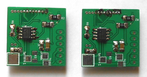
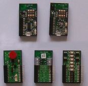
First implementation of the device.
Side with the operational amplifier:
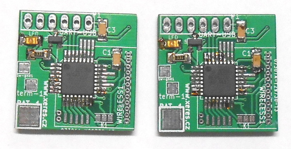
Side with the processor:
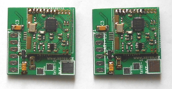
The finished device after soldering the wireless module:
Články na podobné téma
Jak zrychlit web
Rector: upgrade PHP aplikace
Programovací jazyk Go
Analýza zadání a nacenění vývoje softwarového projektu
Python program na ovládání Dockeru pomocí API
Jak použít aplikaci MailCatcher pro testování emailů
Návod: Python OpenAI API
Vytvoření WebSocket webové aplikace a nastavení proxy
Řízení projektů: Agilní vývoj softwaru
Jak provozovat staré PHP aplikace
Co by měl umět dobrý programátor
Programovací jazyk Rust
NodeJS: vývoj, konfigurace serveru
Nette security bug CVE-2020-15227
Jak porovnat dvě stejné databáze?
REST API: API platform
Vlastní web a mail hosting se softwarem ISP Config
Programovní v SQL: PostgreSQL, MySQL/MariaDB
HTTPS: zabezpečený web
NoSQL databáze Mongo DB
Připojení k Microsoft SQL Serveru z Linuxu
Co je pracovní náplň programátora
Lokalizace aplikací v jazyce Python
Jaký mail a web hosting vybrat
Digispark - Programujte mikrokontrolér Atmel ATtiny pomocí Arduino IDE
Program Roulette
Vývoj pro procesory ARM s Arduino IDE
Wireless low power Arduino
Pyradio - Python program for receive Internet radio with text user inteface
UPS monitor pro Android
Bezdrátový bateriově napájený WiFi teploměr
Jak programovat WiFi procesor ESP8266
Comparison IQRF vs Wireless Arduino
Jakou platformu zvolit pro eshop? Například Prestashop
Development kits and gateways for wireless platform IQRF
OpenStreetMap a GPS trasy v mapě na webu
Quickplay
Java program pro přehledné monitorování záložních zdrojů
Čipové kontaktní a bezkontaktní karty Java Card OpenPlatform
Otevřený chytrý telefon s Linuxem - Openmoko Neo FreeRunner
Vývoj pro bezdrátové moduly s procesorem PIC pod GNU/Linux - IQRF
Grafický program pro embeded/mobilní zařízení na vyhledávání dopravního spoje.
O programování a ruzné programy v jazyce Java, Python a dalších
Java program a applet Kalkulačka
Java program na výpočet kvadratické rovnice
Odběr novinek
Pokud máte zájem dostávat příležitostně na email novinky.
Můžete se vyplněním emailu registrovat k
odběru novinek.
+